
When a Pipe Joint Leaks Again: Building the Repair History
How to compile an engineering case history for recurring pipe joint leaks. Document ground water head, joint gap displacement, and internal joint seal review.
By Reliance Trenchless Technology4 min read
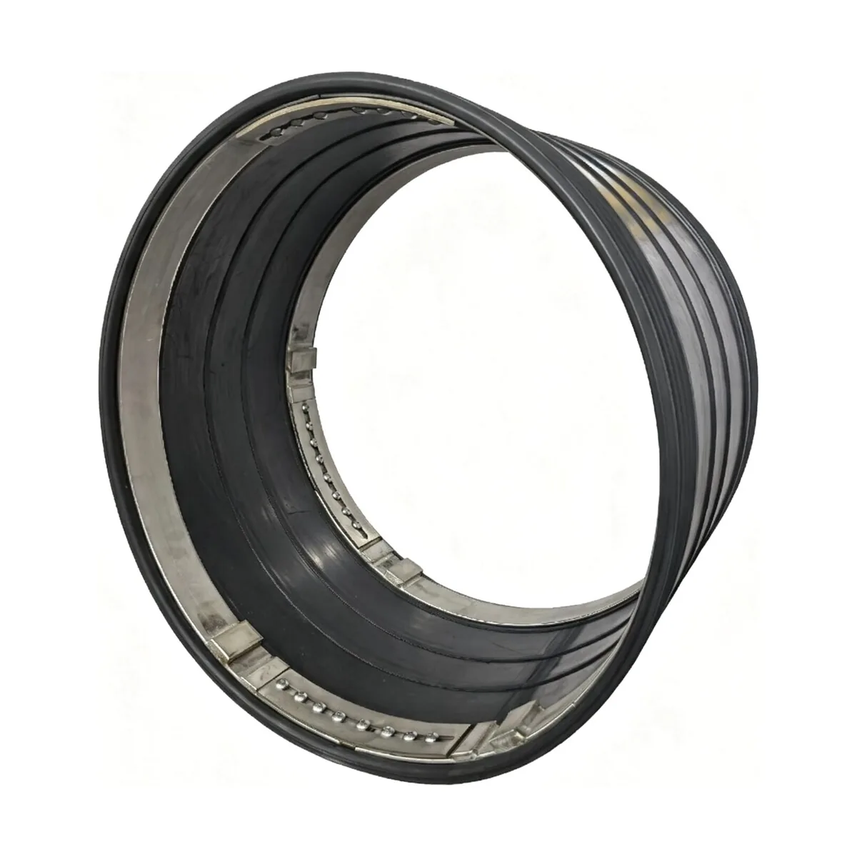
Municipal engineers and asset managers frequently face a frustrating dilemma: a concrete or clay sewer joint that was injected with chemical grout two years ago begins gushing groundwater again during seasonal heavy rains. When a pipe joint leaks repeatedly, continuing to patch it with temporary superficial sealants is a waste of public funds.
What should an asset owner compile when a previously repaired pipe joint fails again? To design a permanent trenchless solution, you must build an engineering case history documenting joint movement mechanisms, groundwater hydrostatic head, past repair material failure modes, and internal pipe roundness.
In the Reliance Internal Pipe Joint Seal Video, internal mechanical joint seals covering diameters from DN150 up to DN4000 are presented, providing permanent joint isolation without excavation. Let us analyze why joints fail repeatedly and how to specify our Internal Pipe Joint Seals as a permanent structural barrier.
Why repetitive chemical grout or temporary patches fail at pipe joints
Pipeline joints are designed as flexible articulators that accommodate ground movement, thermal expansion, and differential soil settlement.
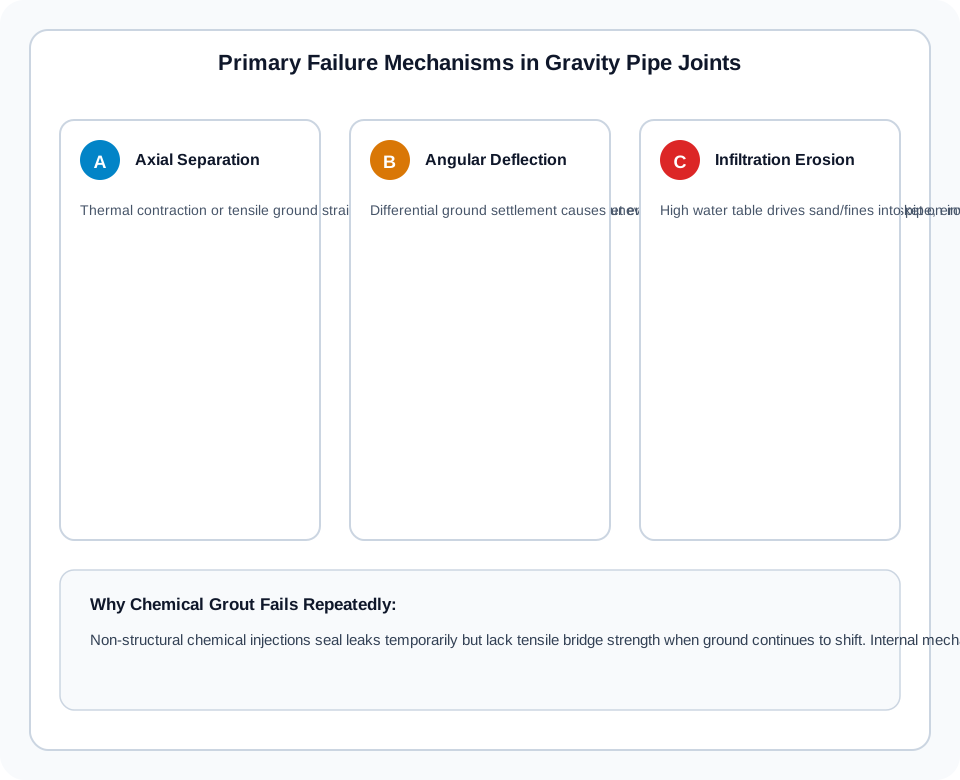
When groundwater infiltrates a joint, field contractors frequently attempt chemical grout injection (polyurethane or acrylamide). While grout can temporarily seal fine voids in the surrounding soil, it fails over time due to three physical failure mechanisms:
Tensile Ground Separation (Axial Pull-Out): Seasonal temperature shifts or tectonic ground creep cause the spigot to withdraw from the bell. Grout lacks tensile elasticity and fractures under axial elongation.
Angular Shear Deflection: Soil compaction differences between adjacent pipe segments cause angular pinching. The joint gasket is crushed on the invert while opening wide at the crown.
Bedding Loss and Hydrostatic Erosion: Once groundwater breaches a chemical patch, rushing water carries sand and silt fines into the pipe, creating hollow voids beneath the joint that accelerate structural sagging.
Compiling the timeline: initial defect, ground movement, and water table records
Before commissioning a permanent mechanical repair, assemble a structured timeline:
Original Pipe Installation Records: Note pipe age, segment length (e.g. 2.5 m concrete vs 1.0 m clay), and original bell-and-spigot joint type.
Previous Intervention Logs: Record the dates, chemical products, and injection pressures used in past repair attempts.
Piezometric Water Table Depth: Measure seasonal maximum groundwater elevation above the pipe invert. An internal seal must be engineered to resist external hydrostatic head pressure (P = ρ · g · h).
Surrounding Traffic Loads: Whether the pipe runs under a heavy commuter highway or railway track that transmits continuous dynamic impact cycles.
Measuring axial gap, angular deflection, and pipe wall roundness
As emphasized in Najafi & Gokhale (2005), specifying an internal mechanical seal requires precise in-situ dimensional surveying rather than relying on nominal pipe drawings:
Joint Gap Width: Measure the axial opening between pipe faces at four points (12, 3, 6, and 9 o'clock). If the gap exceeds 30 mm, an extra-wide bridge profile is required.
Radial Joint Step / Offset: If one pipe barrel has settled lower than the adjoining pipe, measure the step height. Internal mechanical seals accommodate moderate steps through flexible elastomeric profiling.
Circumferential Roundness: Use laser profiling or callipers to confirm the pipe is within acceptable roundness tolerances (typically within ±2% of nominal diameter).
Specifying heavy-duty internal mechanical joint seals (DN150 to DN4000)
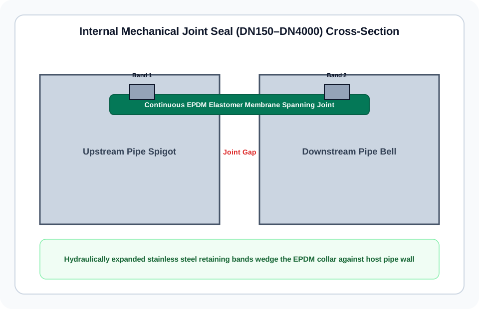
Unlike chemical grout that fills voids outside the pipe, the Reliance Internal Pipe Joint Seal acts from inside the barrel:
Wide EPDM Elastomeric Collar: An engineered rubber sleeve spans completely across the open joint gap, providing a continuous, flexible impermeable barrier meeting ASTM C923 standards.
Hydraulically Expanded Stainless Steel Retaining Bands: Two heavy-gauge stainless steel retaining bands (AISI 304L or 316L) are expanded with a hydraulic spreader tool against the rubber sleeve, compressing it tightly against the host pipe on either side of the joint.
Permanent Dynamic Flexibility: Because the rubber sleeve is not adhered with rigid glue, the host pipe can continue to experience axial thermal movement and angular deflection without breaking the waterproof seal.
Non-Man-Entry to Large Culvert Sizes: Covering diameters from DN150 (installed via pneumatic packer) up to DN4000 (installed manually inside walk-through culverts).
For technical product dimensions, pressure ratings, and hydraulic installation tool kits, visit our Internal Pipe Joint Seal Product Page or submit your joint case history through our Engineering Contact Portal.
References and source documents
Further reading
Article
Disadvantages of Trenchless Pipe Lining: Limits, Failures, and DIY Risks
Article
Sewer Line Replacement: Permits, Insurance Coverage, and Lifespan
Article
Trenchless Sewer Repair Cost per Foot: CIPP, Epoxy, and Point Repairs
Buyer guide
Joint Guide: Measuring Internal Pipe Joint Seals