
Does a Bypass Connection Size Tell You Its Flow Capacity?
Why bypass port diameter alone does not determine flow capacity. Calculate head loss, entrance contractions, and over-pumping flow through pipe plugs.
By Reliance Trenchless Technology3 min read
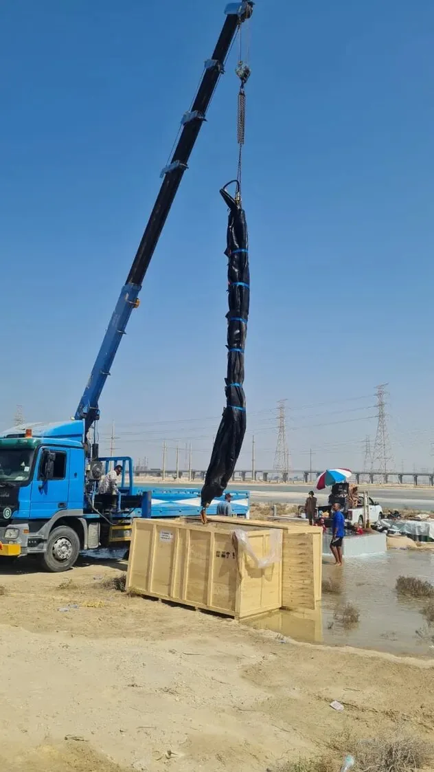
When planning an in-line sewer repair or manhole rehabilitation, site planners often look at a catalogue sheet for a bypass plug, see a "4-inch (DN100) bypass port," and assume it will freely drain their live sewer flow. This assumption frequently ends with flooded basements or overflowing upstream manholes.
Does a bypass connection diameter establish its actual flow capacity? No. A connection diameter is merely a geometric opening; actual flow conveyance is governed by the available hydraulic driving head, minor entrance/exit losses, and conduit friction.
As seen on the heavy-duty bypass plug demonstrated in the Reliance DN800 Bypass Plug Video, robust flanged bypass ports are designed to convey flow while sealing the main line. But using our Single-Size Pipe Plugs or Multi-Size Pipe Plugs effectively requires hydraulic calculations.
Why nominal port diameter is only the geometric starting point
A nominal dimension such as "2-inch" (DN50) or "4-inch" (DN100) defines the cross-sectional area:
A 2-inch port has an internal area of approximately 0.0020 m².
A 4-inch port has an internal area of approximately 0.0081 m² (a 4-fold increase).
A 6-inch port has an internal area of approximately 0.0182 m² (a 9-fold increase over 2-inch).
However, fluid does not accelerate through an orifice without an energy gradient. To achieve high discharge velocity ($v$), there must be a corresponding pressure differential between the upstream and downstream faces of the plug.
Friction loss and hydraulic head driving bypass discharge
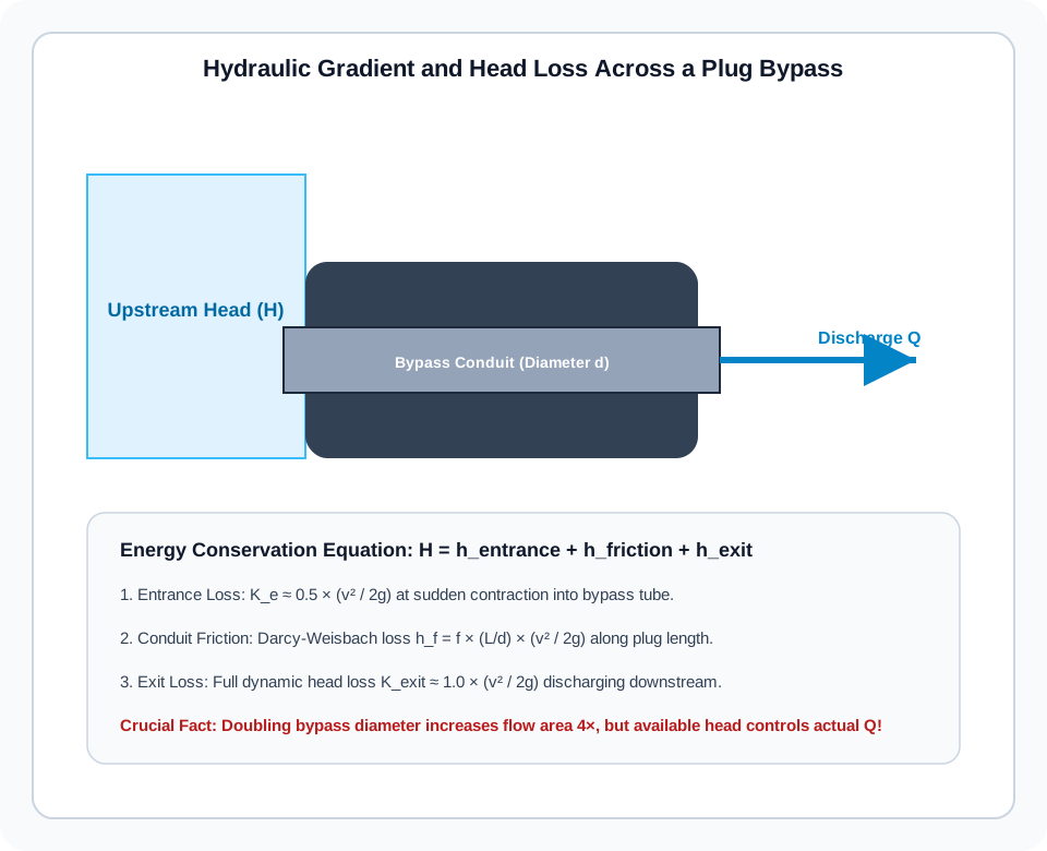
Under standard fluid mechanics principles established in White (2011), the total energy head ($H$) required to pass flow through a plug bypass tube is described by the energy conservation equation:
H = h_entrance + h_friction + h_exit = (K_e + f * L/d + K_exit) * (v^2 / (2g))
Where:
$K_e \approx 0.5$ represents the sharp contraction loss as sewer flow enters the bypass conduit.
$f \frac{L}{d}$ accounts for Darcy-Weisbach pipe friction along the length $L$ of the plug.
$K_{exit} \approx 1.0$ is the dynamic velocity head lost as flow discharges into the downstream channel.
$v = Q / A$ is flow velocity, and $g = 9.81\text{ m/s}^2$.
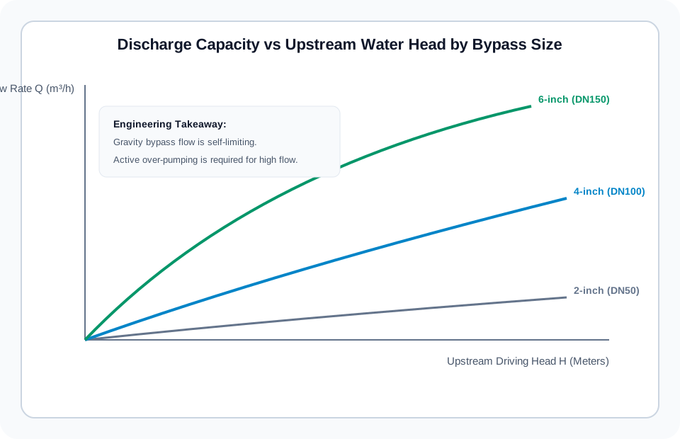
Because $(K_e + K_{exit}) \approx 1.5$, entrance and exit transitions consume substantial head. For a gravity bypass with only 0.3 meters of allowable upstream surcharge in the manhole, a 4-inch bypass tube can only discharge roughly 12 to 15 liters per second (43 to 54 m³/h) before water begins backing up!
Gravity discharge vs pumped bypass connection setups
This hydraulic reality divides bypass plug applications into two distinct operating regimes:
| Feature | Gravity Bypass Mode | Pumped Over-Pumping Mode |
|---|---|---|
| Driving Energy | Upstream water level surcharge | Diesel trash pump suction head |
| Discharge Velocity | Low (< 2.0 m/s) | High (3.0 – 5.0 m/s) |
| Surcharge Risk | High; backup into upstream service laterals | Negligible; pump maintains low sump level |
| Hose Connection | Open downstream discharge tube | Sealed suction hose direct to pump inlet |
As outlined in ASCE Manual of Practice No. 60 for sanitary sewer engineering, if base wet-weather flow exceeds gravity bypass capacity, the bypass plug must be connected directly to a suction pump. Our heavy-duty bypass plugs are manufactured with rigid steel flanged or Camlock connections precisely to support vacuum suction without hose collapse.
Project data needed to verify bypass sizing before trenchless works
To determine whether a standard bypass plug will suffice or if dedicated over-pumping is mandatory, compile these four site values:
Peak Diurnal Flow Rate ($Q_{peak}$): Measure or estimate actual flow during the planned work window (l/s or m³/h).
Maximum Allowable Surcharge Head ($H_{max}$): The maximum elevation water can rise in the upstream manhole before reaching house connection inverts.
Bypass Length & Fittings: The total length of bypass piping or flexible hose routed around the work area, including all elbows and valves.
Suspended Solids Content: Whether raw sewage contains heavy rags or grit that could clog an unmonitored 2-inch or 4-inch internal port.
Check our full catalogue of Single-Size Pipe Plugs and Multi-Size Pipe Plugs, or contact our engineers through our Technical Contact Portal with your flow rates for matched bypass sizing.
References and source documents
Further reading
Article
Disadvantages of Trenchless Pipe Lining: Limits, Failures, and DIY Risks
Article
Sewer Line Replacement: Permits, Insurance Coverage, and Lifespan
Article
Trenchless Sewer Repair Cost per Foot: CIPP, Epoxy, and Point Repairs
Buyer guide
How to Choose an Inflatable Pipe Plug