Reading a DN800 Bypass Pipe Plug Specification
How to interpret a DN800 bypass plug specification. Distinguish 6 bar inflation from 5 bar back pressure, bypass connection sizing, and sewer isolation.
By Reliance Trenchless Technology3 min read
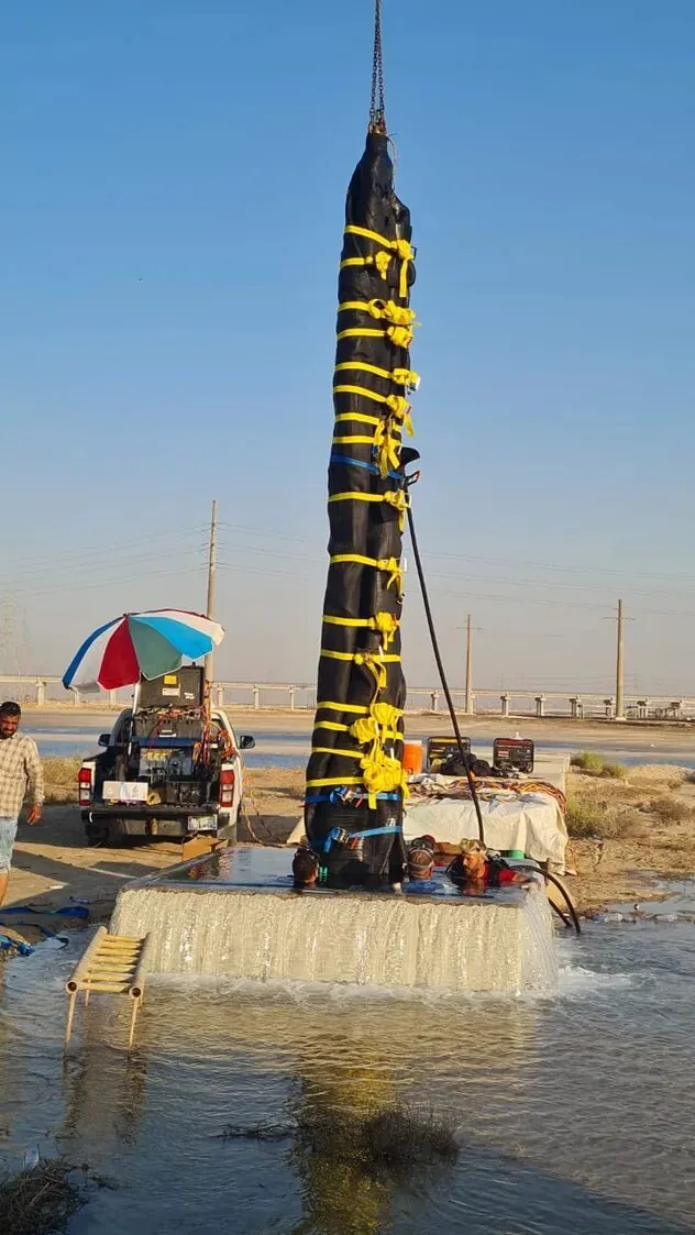
When specifying pipeline isolation tools for an 800 mm (32-inch) sewer interceptor or industrial gravity trunk line, engineers are frequently confronted with specification sheets displaying multiple conflicting pressure ratings. Misreading these figures can lead to catastrophic plug displacement underground.
In the Reliance DN800 High-Pressure Bypass Plug Video, two specific pressure ratings are highlighted: a 6 bar working (inflation) pressure and a 5 bar allowable back pressure, alongside an integrated central bypass. To specify our Single-Size Pipe Plugs correctly, utility engineers must understand how each parameter functions mechanically.
Inflation pressure vs allowable back pressure on heavy-duty plugs
The most critical distinction in pipeline isolation is separating working inflation pressure ($P_{inf}$) from allowable back pressure ($P_{back}$):
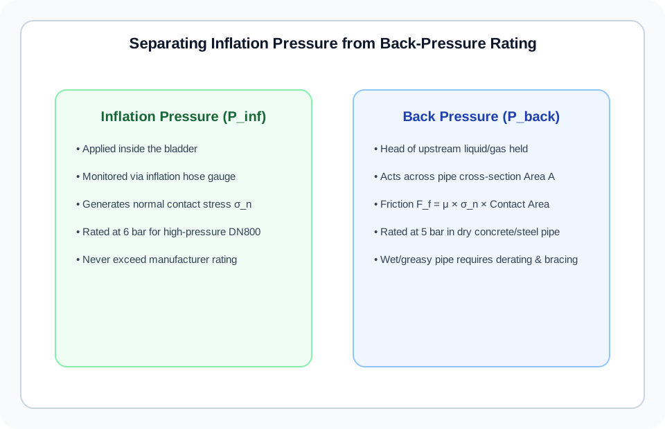
Working Inflation Pressure (6.0 bar): This is the internal pneumatic pressure pumped into the plug bladder through the air valve. It forces the vulcanised rubber body outward, pressing with high normal stress ($\sigma_n$) against the host pipe circumference.
Allowable Back Pressure (5.0 bar): This is the maximum hydrostatic or hydrodynamic pressure the plug can resist from the upstream fluid column without slipping axially along the pipe bore. A 5.0 bar rating corresponds to 50 meters (164 feet) of static water head!
As detailed by Najafi (2010), the plug’s resistance to sliding ($F_{resist}$) is the product of normal contact force and the friction coefficient: $F_{resist} = \mu \cdot \sigma_n \cdot A_{contact}$. If a contractor operates the plug below its rated 6 bar inflation pressure, contact friction drops immediately, drastically compromising the 5 bar back-pressure capability.
Mechanical structure of a high-pressure central bypass core
Standard low-pressure plugs use a flexible rubber bladder with a small hose nipple. In contrast, a heavy-duty DN800 bypass plug incorporates an engineered internal skeleton:
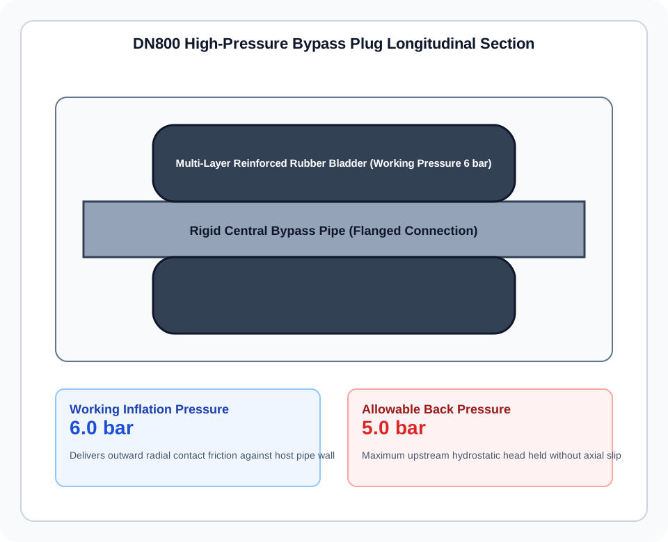
Internal Heavy-Wall Steel Conduit: A seamless structural steel pipe forms the backbone of the plug. It carries axial hydrostatic loads directly through its core rather than transferring tension through unsupported rubber.
Multi-Ply Aramid Cord Reinforcement: The rubber bladder surrounding the steel tube is reinforced with high-modulus aramid fiber belts vulcanised under high temperature and pressure. This prevents ballooning or burst failures at 6 bar working pressure.
Flanged or Threaded Bypass Connections: Standard flanged terminations (e.g. PN10/PN16 or ANSI 150) allow direct bolting of rigid pipe extensions or high-capacity pump suction lines.
Flow conveyance during isolation and over-pumping connections
A bypass plug is deployed when total stoppage of the upstream network is impossible. The central bypass serves three main operational functions:
Controlled Gravity Bypass: Allowing low-flow effluent to pass through the plug during short maintenance windows without flooding upstream basements.
Direct Pumped Over-Pumping: Connecting a suction hose directly to the upstream flange of the plug, allowing high-capacity bypass pumps to draw water straight from the sealed invert.
Water Test Water Injection: Under DIN EN 1610 sewer testing standards, water is injected through the central bypass to fill and pressurize the pipeline section under test while air escapes through a bleed valve.
Verification steps before pressurising a DN800 line
Before introducing 6 bar of compressed air into an 800 mm pipe plug, the site supervisor must verify:
Host Pipe Roundness and Cleanliness: Debris, grease, or heavy calcification will reduce the friction coefficient $\mu$. Pressure-wash the pipe invert at the seat location.
Calibrated Pressure Controller: Always inflate using a pressure controller equipped with a pressure relief valve calibrated to 6.0 bar. Never connect an unregulated industrial compressor directly to the plug.
Downstream Exclusion Zone: Treat any pressurized pipeline plug as a critical containment barrier. Personnel must never enter the zone immediately downstream of an active plug unless secondary mechanical safety bracing is installed.
For full technical specifications on high-pressure bypass units, consult our Single-Size Inflatable Pipe Plugs or request engineering documentation via our Technical Inquiry Page.
References and source documents
Further reading
Article
Disadvantages of Trenchless Pipe Lining: Limits, Failures, and DIY Risks
Article
Sewer Line Replacement: Permits, Insurance Coverage, and Lifespan
Article
Trenchless Sewer Repair Cost per Foot: CIPP, Epoxy, and Point Repairs
Buyer guide
How to Choose an Inflatable Pipe Plug