
Internal Joint Seals vs End Seals: Where Each Fits
A field engineer's guide comparing internal pipe joint seals and CIPP end seals: placement, annular gap sealing, retaining bands, and project data requirements.
By Reliance Trenchless Technology5 min read
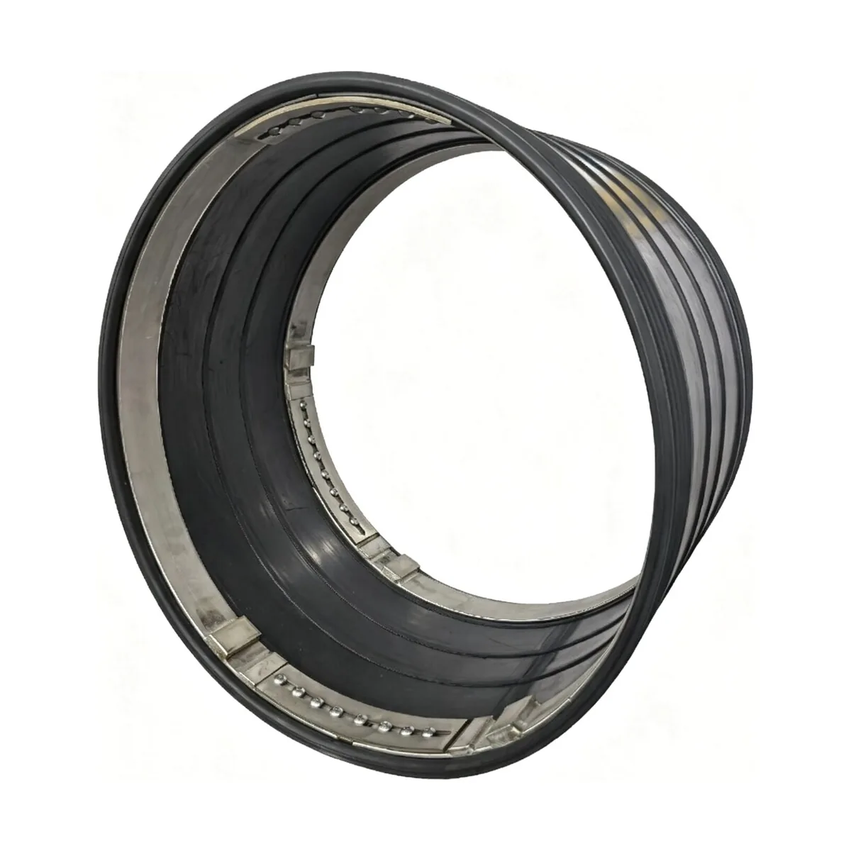
If you see groundwater spurting out around the cut edge of a freshly installed CIPP liner at a manhole wall, ordering an internal joint seal will not solve your problem. An internal joint seal is engineered for pipe-to-pipe barrel joints, not for the stepped annular gap between a host pipe and a cured composite tube. Conversely, placing a stepped end seal over an offset joint mid-run leaves you with an uneven, unsupported gasket that will fail pressure testing.
Mixing up these two mechanical sealing systems is one of the most common—and costly—specification errors in trenchless pipeline rehabilitation. While both rely on high-grade elastomeric sleeves and radial stainless steel expansion bands, they solve entirely different hydraulic and structural problems.
Understanding where each seal fits, how their gasket profiles differ, and what project dimensions you must measure ensures a watertight installation on the first attempt.
1. Where an Internal Joint Seal Is Positioned
An internal pipe joint seal is installed mid-run across individual pipe-to-pipe joints in gravity sewers, stormwater culverts, and low-pressure mains.
When concrete, ductile iron, vitrified clay, or steel pipes experience ground settlement or thermal movement, the factory joint seals deteriorate. Water infiltrates from surrounding water tables, carrying sand and fines that erode pipe bedding and cause road sinkholes.
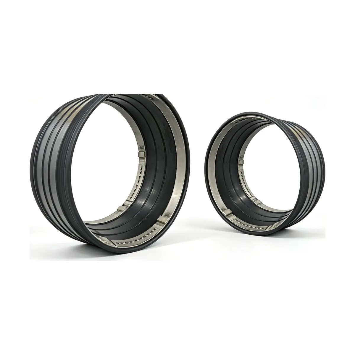
An internal joint seal bridges this discrete joint gap from inside the barrel:
Symmetrical geometry: The heavy-duty EPDM or NBR rubber sleeve features a uniform, symmetrical cross-section with multiple molded sealing ribs along both margins.
Dual expansion bands: High-tensile stainless steel retaining bands (grades 304 or 316) are expanded mechanically against both sides of the joint, driving the sealing ribs into the pipe wall with high radial contact pressure.
Span width: Available in standard widths (typically 250 mm to 500 mm) to span wide joint gaps, angular deflections, or longitudinal crack propagation around the bell-and-spigot socket.
2. Where an Internal End Seal Is Positioned
An internal pipe end seal is installed exclusively at the termination points of a cured-in-place pipe (CIPP) liner—most frequently at manhole entries, outlets, or intermediate liner terminations.
During CIPP installation, thermal or chemical resin shrinkage creates a micro-annular space between the outer surface of the cured liner and the inner wall of the host pipe. Even when the host pipe is completely sealed along its barrel, groundwater under hydrostatic head tracks along this annular space. Without a positive mechanical barrier, this water spills directly into the manhole invert or forces the liner to delaminate over time.
In their comprehensive multi-site study on rehabilitated sewer infrastructure, Allouche et al. (2014) (_Tunnelling and Underground Space Technology_) analyzed exhumed and inspected municipal CIPP installations. Their forensic data demonstrated that annular water migration between the host pipe and liner substrate is a leading root cause of post-rehabilitation infiltration and manhole junction degradation when engineered mechanical end terminations are omitted.
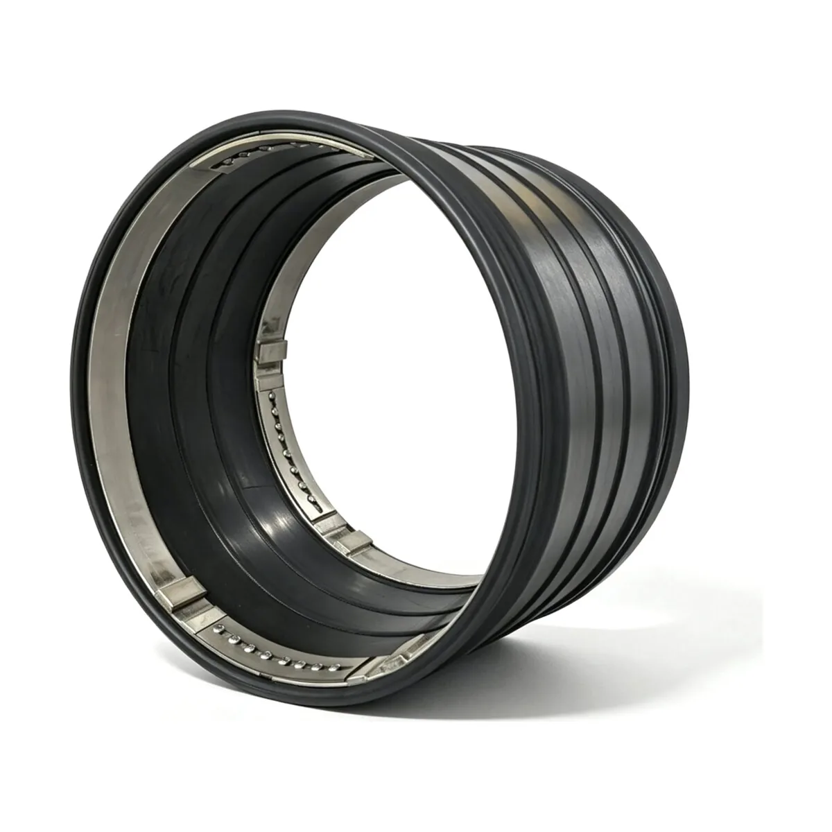
An internal end seal permanently blocks this annular water path through specialized design:
Stepped gasket profile: Unlike flat joint seals, an end seal incorporates an engineered step on its inner face. One section seals against the bare host pipe wall, while the adjacent section seals over the raised outer edge of the CIPP liner.
Annular barrier: A high-compression sealing bulb or hydrophilic rubber element compresses directly into the transition corner, preventing tracking water from bypassing the liner end.
Liner retention: The high-torque expansion band clamps the liner firmly against the host pipe, eliminating the risk of edge curling or hydro-jet cleaning head snagging.
3. Comparing Gasket Profiles, Bands, and Functions
Selecting between the two tools comes down to the structural interface you are sealing:
| Technical Feature | Internal Joint Seal | Internal End Seal |
|---|---|---|
| Primary position | Mid-run pipe-to-pipe barrel joints | Terminus of CIPP liner at manhole or host pipe |
| Rubber cross-section | Symmetrical flat profile with sealing ribs | Stepped profile matching liner wall thickness |
| Defect sealed | Joint gap, offset joint, bell-and-spigot leak | Annular gap between host pipe and CIPP liner |
| Water tracking defense | Seals discrete joint infiltration | Blocks longitudinal tracking behind liner |
| Clamping band setup | 2 to 4 parallel internal expansion bands | 1 to 2 heavy-duty step-compression bands |
| Applicable diameters | DN150 up to DN4000+ | DN150 up to DN1600+ (matched to liner wall) |
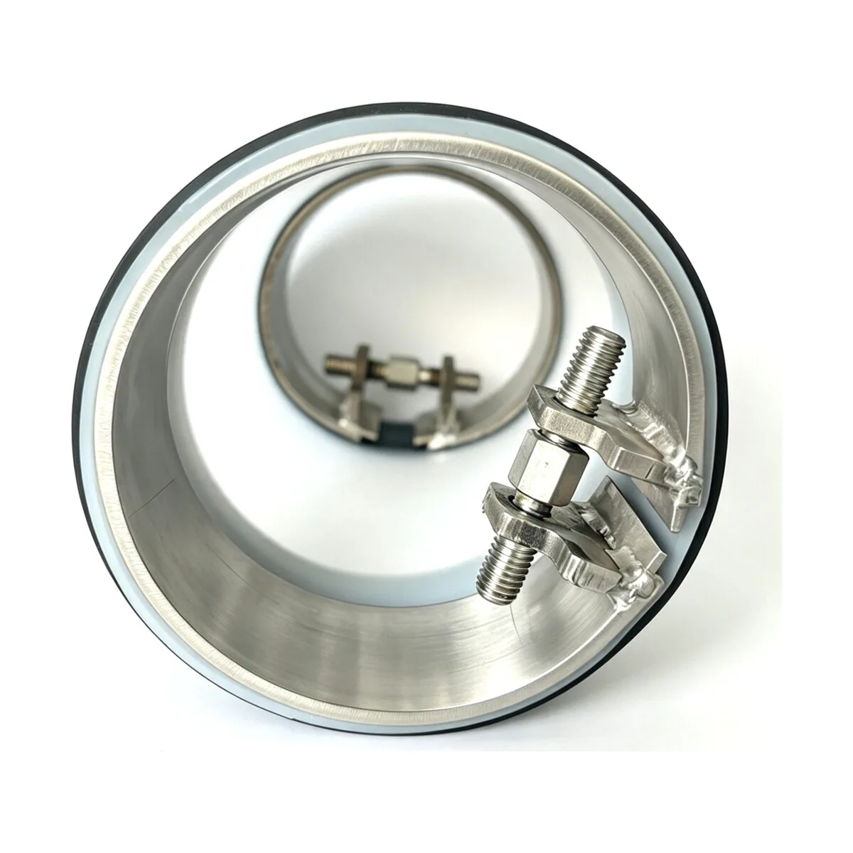
Both systems adhere to the rigorous material standards outlined in NASSCO pipe rehabilitation guidelines and are installed using mechanical or hydraulic expansion tools following UK HSE safe maintenance practices.
4. Measurement Checklist: What Project Data to Collect
Before requesting quotation drawings or ordering seals, gather these exact field measurements:
When Ordering Internal Joint Seals:
[ ] Exact host pipe internal diameter (ID): Measure vertically and horizontally to check for pipe ovality or out-of-roundness.
[ ] Joint gap width: Measure the maximum gap distance between pipe spigot and bell ends.
[ ] Axial or angular joint offset: Record any vertical drop or lip between adjoining pipe segments.
[ ] Pipe material and host condition: Concrete, ductile iron, steel, or clay, including surface corrosion or aggregate exposure.
When Ordering Internal End Seals:
[ ] Host pipe internal diameter (ID): Measured at the manhole face before liner insertion.
[ ] Finished CIPP liner wall thickness: Crucial for selecting the exact step height in the rubber gasket (typically 4 mm to 15 mm).
[ ] Liner cutback distance: Measure how far the cured liner extends into or terminates before the manhole wall face.
[ ] Water table conditions: Estimated hydrostatic head pressure to confirm retaining band torque requirements.
For step-by-step field measuring techniques, review our internal pipe joint seals measurement guide and our comparison with internal repair sleeves.
Next Steps for Your Sealing Project
Whether you are sealing leaking RCP joint rings or protecting CIPP liner terminations against annular infiltration, choosing the correct seal profile ensures permanent watertight integrity.
Check verified dimensions in our Reliance technical brochure and specification spreadsheet, or submit your pipe diameters, liner thicknesses, and site conditions via our internal seal project enquiry for tailored drawings and sizing recommendations.
References and source documents
Further reading
Article
Disadvantages of Trenchless Pipe Lining: Limits, Failures, and DIY Risks
Article
Sewer Line Replacement: Permits, Insurance Coverage, and Lifespan
Article
Trenchless Sewer Repair Cost per Foot: CIPP, Epoxy, and Point Repairs
Buyer guide
Joint Guide: Measuring Internal Pipe Joint Seals
Buyer guide
Internal Pipe Joint Seals vs Repair Sleeves: What Is the Difference?