How a Pipe Plug Holds Back Sewer Head: Pressure, Area and Friction
How a 2.5 kg pipe plug resists 700 kgf of sewer water. Explore the physics of back pressure, contact grip, and multi-size expansion from our YouTube explainer.
By Reliance Trenchless Technology8 min read
Continue with AI
Bring this article into your own conversation.
Preferred Sources
Keep up with Reliance Trenchless on Google.
Availability depends on your account and region.
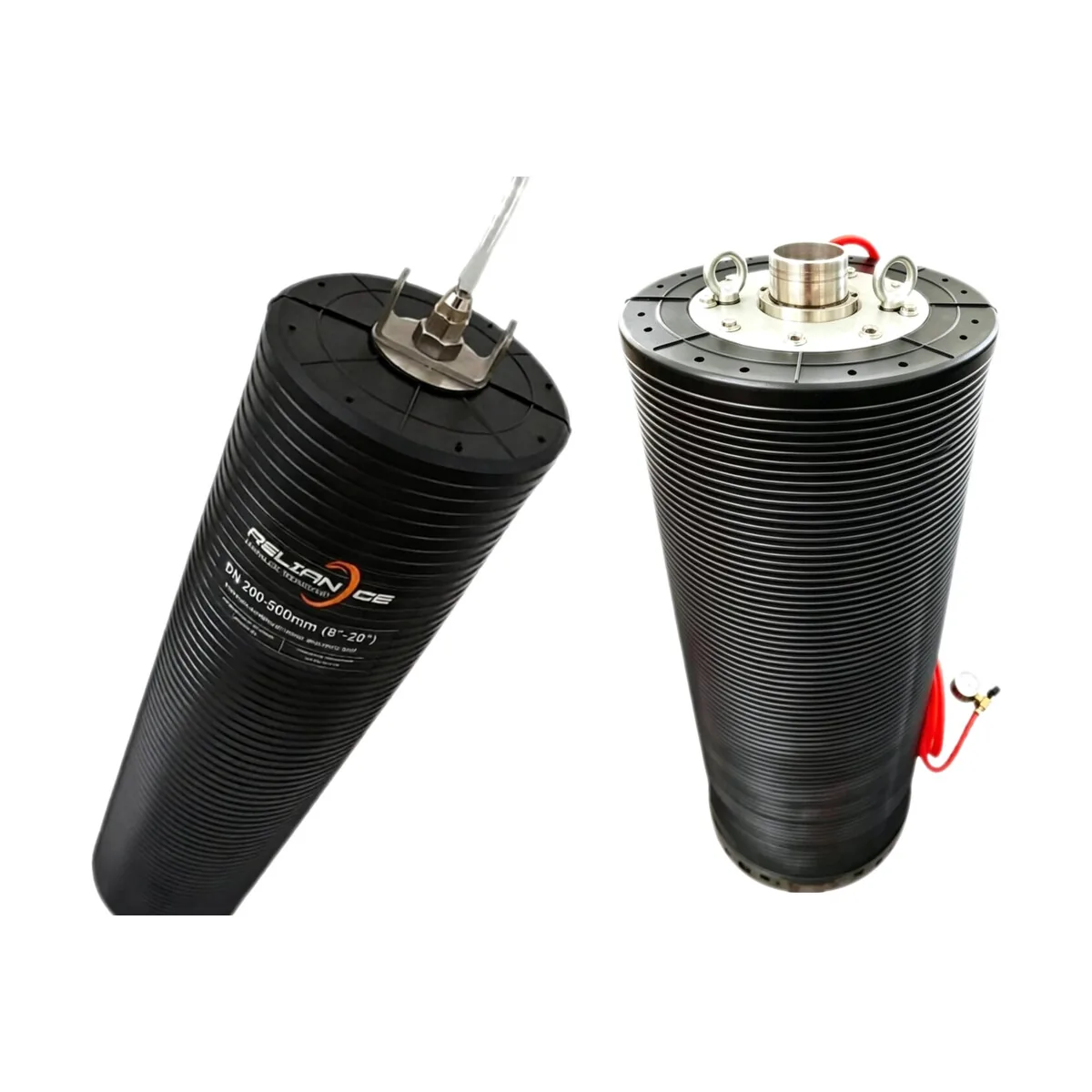
A standard multi-size pipe plug like the MS 150-300 weighs roughly 2.5 kg. Yet when inserted into an active DN300 gravity sewer and inflated to its rated working pressure, that single piece of vulcanized elastomer holds back an upstream hydraulic thrust exceeding 7,000 Newtons—over 700 kilograms of pushing force.
Pipeline contractors, rehabilitation crews, and municipal utility engineers need to know how a flexible rubber cylinder counteracts hydrostatic loads. In our dedicated video explainer, How a Multi-Size Pipe Plug Holds Back a Sewer: Pressure, Area and Grip (also available on YouTube), we break down the physics that governs sewer isolation: the relationship between fluid pressure and cross-sectional area, the scaling laws of conduit diameter, and the contact friction generated along the pipe perimeter.
The Governing Physics: Calculating Hydrostatic Thrust
Gravity sewers operate under continuous incoming flow. When a pipeline is plugged for CCTV inspection, sectional point repair, or low-pressure air testing under ASTM F1417-25, the effluent halts and begins accumulating behind the barrier. This creates an upstream liquid column known as head or back pressure ().
Back pressure exerts normal force across every unit area of the plug face. The total axial thrust driving the plug downstream is defined by fundamental fluid statics:
Converting units shows the force that modest field pressures produce:
1.0 bar equals 100 kPa or approximately (roughly 10.2 metres of hydrostatic water column).
A DN300 pipe (internal diameter ) has an internal cross-sectional area .
At 1.0 bar of rated back pressure, the total axial push against the plug face is:
A crew standing in the downstream manhole is separated from nearly three-quarters of a metric ton of water push by a single pneumatic seal.
The Square-Law Scaling Effect on Pipe Diameter
Hydrostatic thrust does not increase linearly with pipe size; it scales with the square of the diameter (). Doubling the internal conduit diameter quadruples the cross-sectional face area:
In a DN150 pipe, . At 1.0 bar back pressure, thrust is roughly (~180 kgf).
In a DN300 pipe, (4× area). At 1.0 bar back pressure, thrust reaches (~720 kgf).
In a DN600 pipe, (16× area of DN150). Even at a reduced back pressure of 0.5 bar (), thrust reaches (~1,440 kgf).
In a DN1200 trunk sewer, (64× area of DN150). At just 0.2 bar back pressure (, equivalent to 2 metres of water head), the axial push is (~2,306 kgf).
Because thrust rises with the square of the diameter while anchoring is limited, the published back-pressure rating falls as nominal diameter increases.
The Mechanics of Grip: Contact Pressure vs Friction
A smooth, lubricated rubber plug stays in place through interface contact mechanics and shear friction.
As analyzed in academic research by Persson (2001) on the theory of rubber friction and contact mechanics, elastomeric materials under normal loading deform viscoelastically into the microscopic asperities of rigid substrates such as concrete, clay, or PVC pipe walls. When an inflatable plug is pressurized with compressed air (), its outer rubber jacket expands outward, exerting a radial contact stress across the cylindrical contact area (, where is the effective contact length):
The total frictional holding resistance () that counteracts upstream hydrostatic push is:
where is the effective static friction coefficient between the vulcanized rubber carcass and the host pipe surface.
To guarantee zero downstream sliding, the system requires that:
where is the engineering safety factor (typically to ).
This relationship sets the operating rule shown in our video explainer: Internal inflation pressure must always exceed rated back pressure (). On the Reliance Multi-Size Pipe Plug MS 150-300, internal inflation pressure is maintained at 2.0 bar, while maximum allowable back pressure is limited to 1.0 bar. If internal pressure drops below back pressure, the hydraulic head lifts the rubber away from the pipe crown, destroying normal contact stress and expelling the plug downstream.
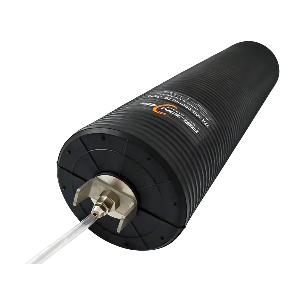
Multi-Size Architecture: Nylon Reinforcement and Folding
How can one plug span diameters from DN150 up to DN300 without bursting or losing hoop integrity?
Standard single-size plugs rely on molded rubber with limited radial elasticity. In contrast, multi-size plugs incorporate an internal multi-ply carcass made from high-polymer nylon cords vulcanized between layers of weather-resistant and chemical-resistant synthetic rubber.
Deflated Profile for Restricted Manholes: When deflated, the MS 150-300 collapses to a maximum outer diameter of only 135 mm. This compact envelope allows field crews to slip the unit through tight manhole openings, drop drops, and shallow inspection shafts without excavation.
Even Expansion Envelope: Upon inflation, the nylon cord grid guides the radial stretching of the rubber matrix, ensuring uniform wall contact without asymmetric bulging or localized thinning.
Molded Circumferential Ribs: The exterior circumference features molded annular sealing ribs. These ribs concentrate radial normal stress onto narrow contact bands, displacing lingering boundary water films and maximizing interface grip against smooth plastic or slime-coated clay pipes.
| Model | Deflated OD (mm) | Sealing Range (DN mm) | Inflation Pressure (bar) | Max Back Pressure (bar) | Total Thrust at Max Rating (kN / kgf) |
|---|---|---|---|---|---|
| MS 50-100 | 47 | 50–100 | 3.0 | 2.0 | 1.57 kN / 160 kgf |
| MS 70-150 | 67 | 70–150 | 3.0 | 2.0 | 3.53 kN / 360 kgf |
| MS 100-200 | 95 | 100–200 | 2.0 | 1.0 | 3.14 kN / 320 kgf |
| MS 150-300 | 135 | 150–300 | 2.0 | 1.0 | 7.07 kN / 721 kgf |
| MS 200-400 | 182 | 200–400 | 2.0 | 1.0 | 12.57 kN / 1,281 kgf |
| MS 200-500 | 185 | 200–500 | 2.0 | 1.0 | 19.63 kN / 2,002 kgf |
| MS 300-600 | 283 | 300–600 | 1.5 | 0.5 | 14.14 kN / 1,441 kgf |
| MS 400-800 | 365 | 400–800 | 1.5 | 0.5 | 25.13 kN / 2,563 kgf |
| MS 500-1000 | 460 | 500–1000 | 1.5 | 0.5 | 39.27 kN / 4,004 kgf |
| MS 600-1200 | 550 | 600–1200 | 1.2 | 0.2 | 22.62 kN / 2,306 kgf |
Essential Safety Protocols for Site Crews
Under guidance from the UK HSE GS4 (2012) safety standard for pressure testing, an inflated pipe plug holding compressed air and high-head fluid represents a significant stored energy source (). If dynamic failure or slippage occurs, the plug releases that energy instantly.
Crews apply four field rules to each isolation:
Clean the Pipe Invert Before Sealing: Per NASSCO assessment guidelines, grease, silt, organic biofilm, and mineral encrustation severely reduce the static friction coefficient . Always perform jetting or mechanical scraping along the seating zone before inflating.
Calibrate Inflation Gauges: Always monitor inflation through a dedicated controller fitted with a certified pressure gauge and safety relief valve. Never guess inflation by pump run time or tactile stiffness.
Continuous Back-Pressure Monitoring: Upstream surcharge can escalate rapidly during rainfall or unexpected industrial discharges. If upstream head exceeds the model's published back-pressure rating, relieve flow via a bypass plug or install secondary isolation upstream.
Install Positive Mechanical Bracing: Never stand or work directly in the line of projection downstream of an unbraced pneumatic plug during live sewer flow or high-pressure acceptance testing. Install structural trench shores, timber cribbing, or mechanical pipe braces downstream to absorb unexpected shock loads.
Frequently Asked Questions About Sewer Head and Plug Grip
How much back pressure can a multi-size plug hold in a DN300 sewer?
The MS 150-300 is rated at 2.0 bar inflation pressure and a maximum back pressure of 1.0 bar. At that rating, the axial thrust on the plug face in a DN300 pipe is about 7.07 kN, or 721 kgf (table above). The figure belongs to this model over its 150–300 mm sealing range, so confirm the measured internal diameter and the current rating with Reliance before the isolation.
Why do larger plugs carry lower back-pressure ratings?
Thrust rises with the square of the internal diameter, so the same head pushes harder on a larger plug face. A DN600 line has about 16 times the cross-sectional area of DN150, and the MS 300-600 is rated at 0.5 bar while the MS 50-100 is rated at 2.0 bar. Use the published rating for the model you will use, because pipe size alone does not set the limit.
Why must inflation pressure stay above back pressure?
The inflation pressure produces the radial contact stress that generates friction at the pipe wall. If upstream head exceeds internal pressure, the rubber lifts away from the pipe crown, contact stress falls and the plug can be expelled downstream. Every model in the table keeps its inflation pressure above its maximum back pressure.
Do grease and sediment reduce the holding force?
Yes. The holding force depends on the friction coefficient between the rubber and the pipe wall, and grease, silt, biofilm and mineral encrustation lower that coefficient at the same inflation pressure. NASSCO assessment guidance covers pipe condition, and the field rules above call for jetting or scraping the seating zone before inflation. Confirm the cleaning method and seating length for the actual pipe.
Will a multi-size plug pass through the manhole?
A deflated MS 150-300 measures 135 mm across, and a deflated MS 600-1200 measures 550 mm. Compare the deflated diameter with the narrowest opening on the access route, then check the sealing range against the measured pipe bore. Submit the manhole and pipe dimensions to Reliance for a model check.
Confirm the Rating for Your Line
For detailed equipment sizing, consult the Inflatable Pipe Plug Selection Guide, or submit your pipe diameter and working pressure via Reliance Technical Enquiries for engineering verification.
References and source documents
Further reading
Article
Pipe Leak and Break Repair: Joint Seal, Sleeve, Patch or CIPP?
Article
Inflatable Pipe Plug Names: A Quotation Checklist
Article
Pipe Repair Kit: Matching Packers, Resin and Fiberglass
Buyer guide
How to Choose an Inflatable Pipe Plug